二維應力Plane Stress
單軸拉力的斜截面 Stress on an Oblique Plane
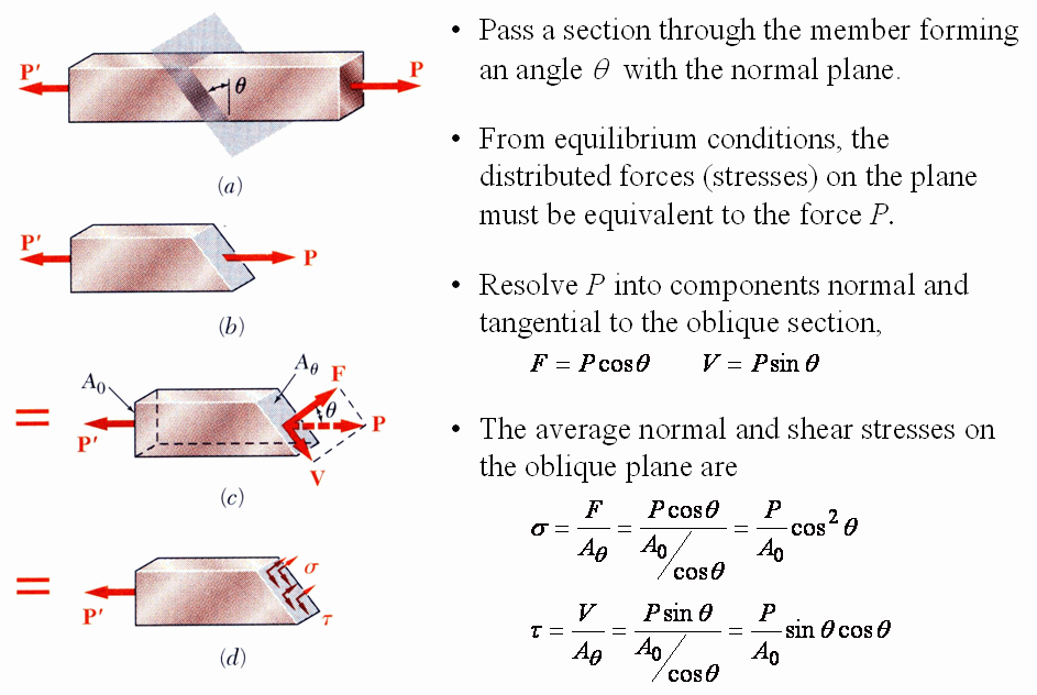
- 以與橫截面夾 \(\theta\) 的斜面切開;由平衡,斜面上的分佈力必須等效於 \(P\)。
- 把 \(P\) 分解成斜面的法向與切向分量:\(F=P\cos\theta\)、\(V=P\sin\theta\)。
- 斜面面積 \(A_\theta=A_0/\cos\theta\),平均應力:
補充:\(\theta=0\) 時 \(\sigma=P/A_0\) 最大、\(\tau=0\);\(\theta=45^\circ\) 時 \(\tau_{max}=\dfrac{P}{2A_0}\)。延性材料拉伸時沿 45° 面滑移,正是剪應力造成的。
原圖對照(斜截面)
平面應力狀態 State of Plane Stress
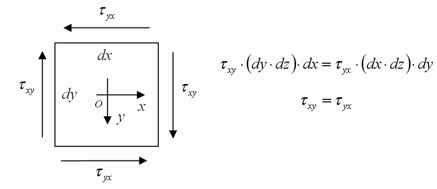
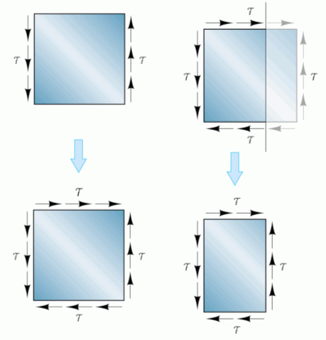
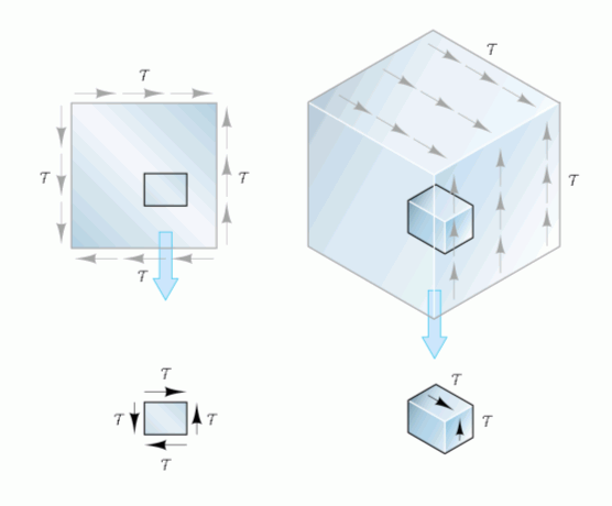
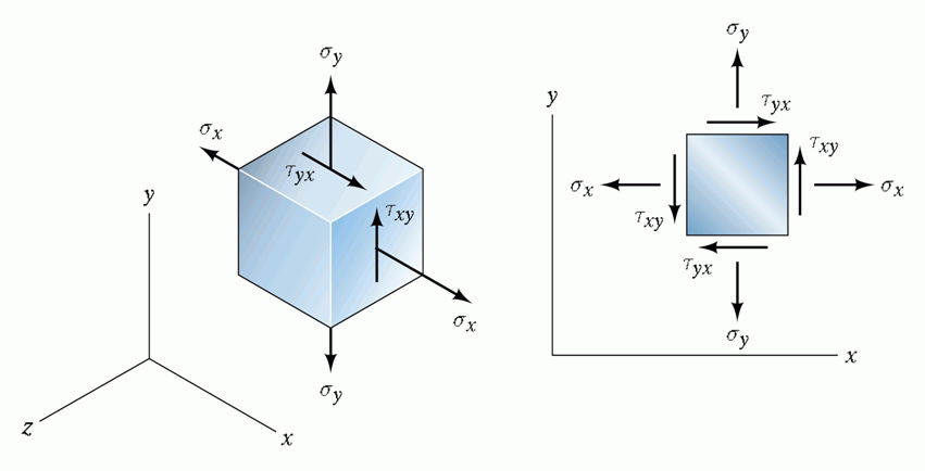
- 互補剪應力:元素對 z 軸的力矩平衡 \(\tau_{xy}(dy\,dz)\,dx=\tau_{yx}(dx\,dz)\,dy\),所以 \(\tau_{xy}=\tau_{yx}\)。四個面上的剪應力大小相等,兩兩組成方向相反的力偶。
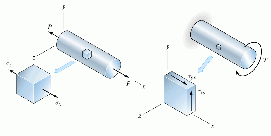
- 平面應力:只有 \(\sigma_x\)、\(\sigma_y\)、\(\tau_{xy}\),z 方向的應力都為 0。軸受拉(只有 \(\sigma_x\))、受扭(只有 \(\tau_{xy}\))、梁的表面等都是這種狀態。
- 符號規則(沿用原講義):正向應力拉為正;剪應力使元素順時針轉者為正(上圖右面向下、左面向上)。
編註:Hibbeler、Gere 等多數教科書規定 +x 面上指向 +y 的剪應力為正(右面向上),恰與本講義相反;換用那套規則時,下面公式中的 \(\tau_{xy}\) 項要變號,莫爾圓的畫法也跟著不同,但主應力、最大剪應力的大小完全一樣。
原圖對照(平面應力)
應力轉換 Stress Transformation
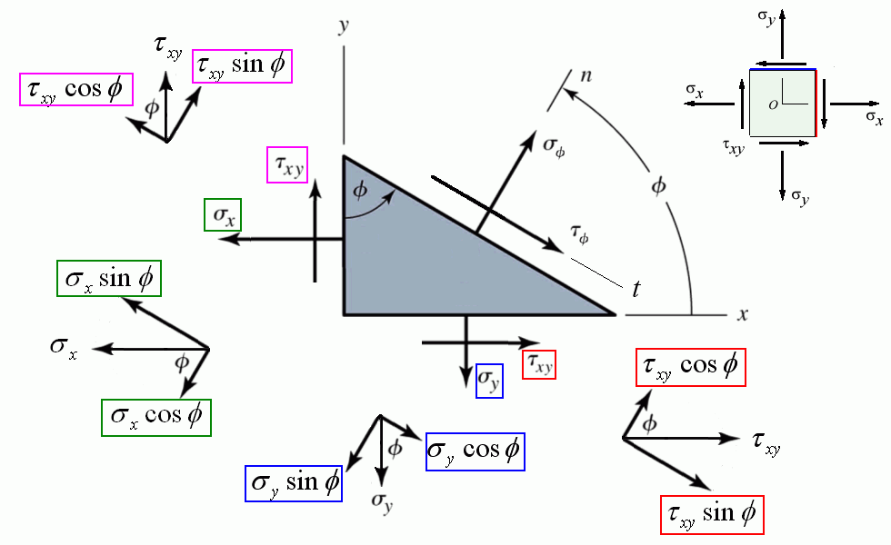
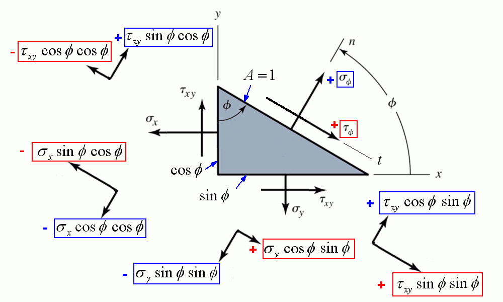
斜面面積取 1,則左面積 \(\cos\phi\)、底面積 \(\sin\phi\);斜面外法線 \(n\) 與 x 軸夾 \(\phi\)。沿 \(n\) 方向的力平衡:
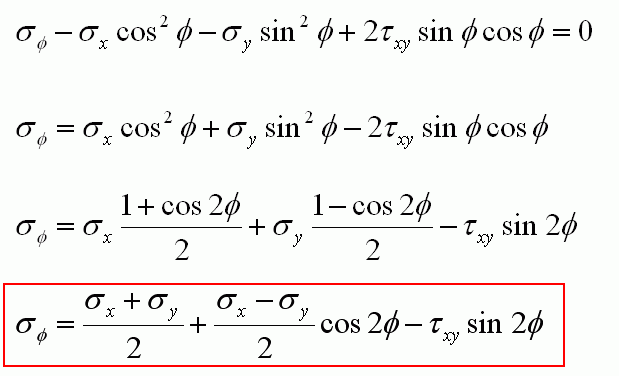
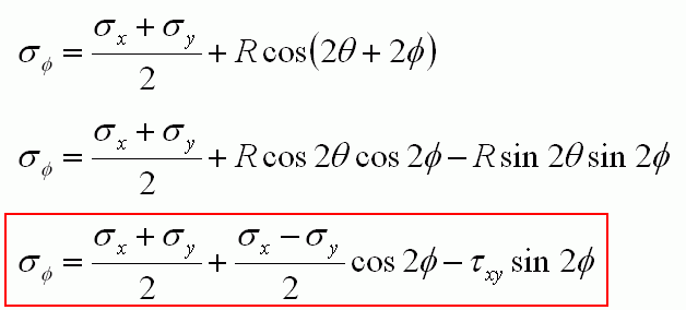
$$\sigma_\phi-\sigma_x\cos^2\phi-\sigma_y\sin^2\phi+2\tau_{xy}\sin\phi\cos\phi=0$$用倍角公式整理:
$$\boxed{\sigma_\phi=\frac{\sigma_x+\sigma_y}{2}+\frac{\sigma_x-\sigma_y}{2}\cos2\phi-\tau_{xy}\sin2\phi}$$沿斜面 \(t\) 方向的力平衡:
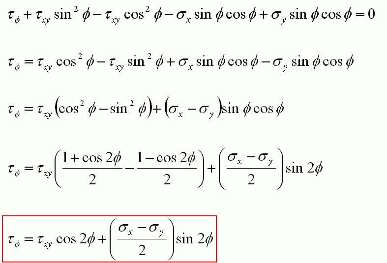
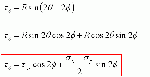
$$\tau_\phi+\tau_{xy}\sin^2\phi-\tau_{xy}\cos^2\phi-\sigma_x\sin\phi\cos\phi+\sigma_y\sin\phi\cos\phi=0$$ $$\boxed{\tau_\phi=\tau_{xy}\cos2\phi+\frac{\sigma_x-\sigma_y}{2}\sin2\phi}$$補充:把 \(\phi\) 換成 \(\phi+90^\circ\) 可得另一面的正向應力,兩者相加 \(\sigma_\phi+\sigma_{\phi+90^\circ}=\sigma_x+\sigma_y\):互相垂直的兩面正向應力和不隨方向改變(不變量)。
原圖對照(應力轉換推導)
莫爾圓 Mohr's Circle
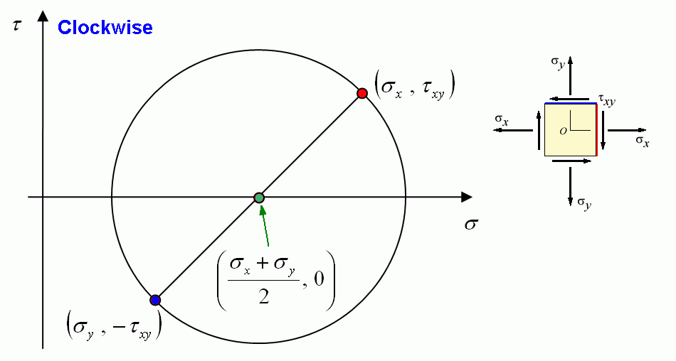
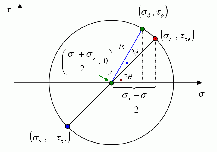
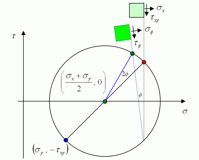
令圓心 \(C\)、半徑 \(R\),並把 X 面的狀態 \((\sigma_x,\tau_{xy})\) 看成圓上與 σ 軸夾 \(2\theta\) 的一點:
- 與上一節的轉換公式完全相同,所以任一截面的 \((\sigma_\phi,\tau_\phi)\) 都落在以 \((C,0)\) 為圓心、\(R\) 為半徑的圓上(補充:消去 \(\phi\) 即得 \((\sigma_\phi-C)^2+\tau_\phi^2=R^2\))。
- X 面在 \((\sigma_x,\tau_{xy})\),Y 面在 \((\sigma_y,-\tau_{xy})\),兩點是直徑的兩端。
- 元素轉 \(\phi\),圓上的點轉 \(2\phi\),方向相同(剪應力以順時針為正、畫在上方時)。
互動莫爾圓(補充):拖曳滑桿改變應力或轉角。左圖是轉 φ 後的元素(藍:正向應力,橘:剪應力),右圖綠點是該面在莫爾圓上的位置;按「轉到主應力方向」時剪應力消失。單位任意(例如 MPa)。
原圖對照(莫爾圓)
主應力與最大剪應力 Principal Stresses
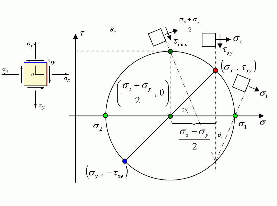
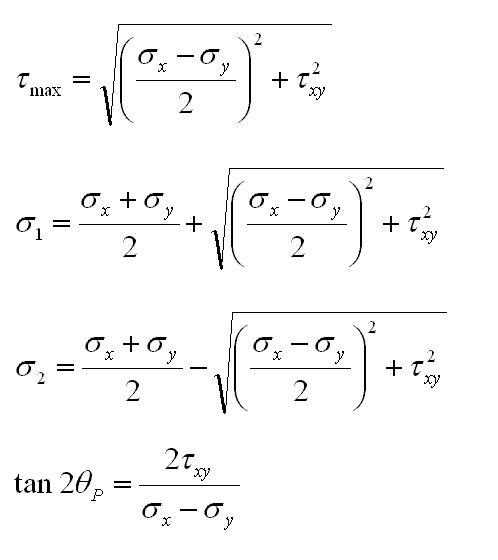
莫爾圓與 σ 軸的兩個交點,就是所有方向中最大、最小的正向應力(主應力),該面上剪應力為 0;圓的最高點是最大剪應力:
- 兩個主平面互相垂直;最大剪應力面與主平面相差 45°,其上的正向應力等於 \(C=\dfrac{\sigma_x+\sigma_y}{2}\)。
- \(\tan2\theta_p\) 在 0–180° 間有兩個解,對應 \(\sigma_1\)、\(\sigma_2\) 兩個主方向;要分辨哪一個是 \(\sigma_1\),最穩當的方法是代回 \(\sigma_\phi\) 公式,或直接看莫爾圓。
- 這裡的 \(\tau_{max}\) 是平面內的最大剪應力;若 \(\sigma_1\)、\(\sigma_2\) 同號,真正的最大剪應力在面外,見下一頁應力張量的三維莫爾圓。
原圖對照(主應力)
例題 1 Example 1
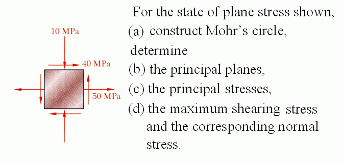
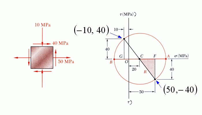
對圖示的平面應力狀態(MPa):(a) 畫莫爾圓;求 (b) 主平面、(c) 主應力、(d) 最大剪應力與該面上的正向應力。
For the state of plane stress shown, (a) construct Mohr's circle, determine (b) the principal planes, (c) the principal stresses, (d) the maximum shearing stress and the corresponding normal stress.
\(\sigma_x=50\)、\(\sigma_y=-10\);右面的剪應力 40 MPa 向上,使元素逆時針轉,依本講義規則 \(\tau_{xy}=-40\) MPa。
(a) 莫爾圓:X 面在 \((50,-40)\)、Y 面在 \((-10,40)\):
$$C=\frac{50+(-10)}{2}=20,\qquad R=\sqrt{30^2+40^2}=50\ \text{MPa}$$(b)(c) 主平面與主應力:
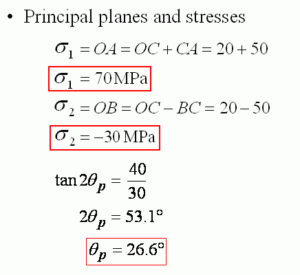
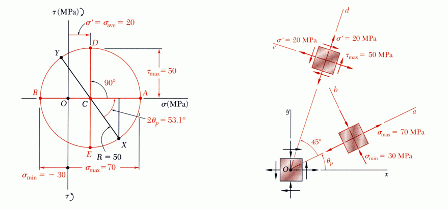
$$\sigma_1=OA=OC+CA=20+50=70\ \text{MPa},\qquad \sigma_2=OB=OC-BC=20-50=-30\ \text{MPa}$$ $$\tan2\theta_p=\frac{40}{30}\ \Rightarrow\ 2\theta_p=53.1^\circ\ \Rightarrow\ \theta_p=26.6^\circ\ (\text{逆時針})$$(d) 最大剪應力與對應的正向應力:
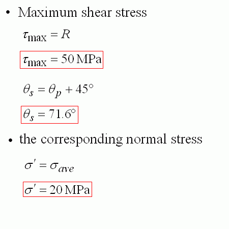
$$\tau_{max}=R=50\ \text{MPa},\qquad \theta_s=\theta_p+45^\circ=71.6^\circ,\qquad \sigma'=\sigma_{ave}=20\ \text{MPa}$$原圖對照(例題 1)
例題 2 Example 2
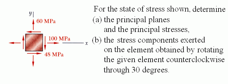
對圖示的應力狀態(MPa),求 (a) 主平面與主應力;(b) 元素逆時針轉 30° 後各面上的應力分量。
(a) the principal planes and the principal stresses, (b) the stress components exerted on the element obtained by rotating the given element counterclockwise through 30 degrees.
\(\sigma_x=100\)、\(\sigma_y=60\);右面剪應力 48 MPa 向下(順時針),\(\tau_{xy}=+48\) MPa。
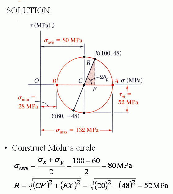
(a) 莫爾圓與主應力:
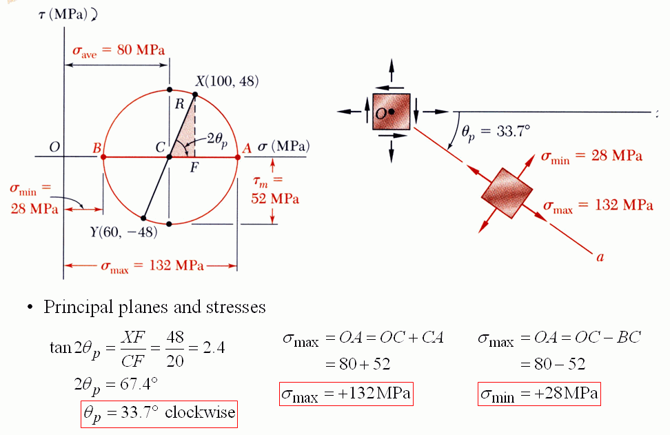
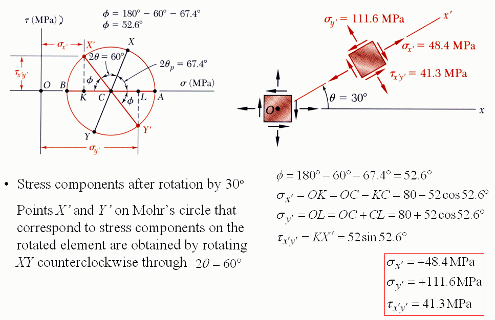
$$\sigma_{ave}=\frac{100+60}{2}=80\ \text{MPa},\qquad R=\sqrt{(CF)^2+(FX)^2}=\sqrt{20^2+48^2}=52\ \text{MPa}$$ $$\tan2\theta_p=\frac{XF}{CF}=\frac{48}{20}=2.4\ \Rightarrow\ 2\theta_p=67.4^\circ\ \Rightarrow\ \theta_p=33.7^\circ\ (\text{順時針})$$ $$\sigma_{max}=OC+CA=80+52=132\ \text{MPa},\qquad \sigma_{min}=OC-BC=80-52=28\ \text{MPa}$$(b) 元素逆時針轉 30°,莫爾圓上 XY 直徑也逆時針轉 \(2\theta=60^\circ\) 到 X′Y′。X′ 與 σ 軸的夾角:
$$\phi=180^\circ-60^\circ-67.4^\circ=52.6^\circ$$ $$\sigma_{x'}=OK=OC-KC=80-52\cos52.6^\circ=48.4\ \text{MPa}$$ $$\sigma_{y'}=OL=OC+CL=80+52\cos52.6^\circ=111.6\ \text{MPa}$$ $$\tau_{x'y'}=KX'=52\sin52.6^\circ=41.3\ \text{MPa}$$補充:直接代第一批的轉換公式(\(\phi=30^\circ\))也得到同樣結果:\(\sigma_{x'}=80+20\cos60^\circ-48\sin60^\circ=48.4\)、\(\tau_{x'y'}=48\cos60^\circ+20\sin60^\circ=41.3\) MPa。
原圖對照(例題 2)
常見負載的應力狀態 Stress States of Basic Loadings
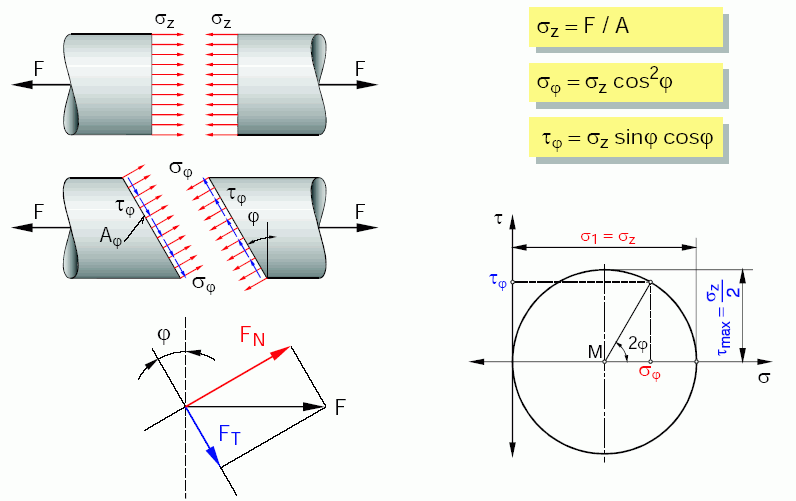
- 拉伸:\(\sigma_z=F/A\),莫爾圓通過原點與 \(\sigma_z\);與橫截面夾 \(\varphi\) 的斜面上 \(\sigma_\varphi=\sigma_z\cos^2\varphi\)、\(\tau_\varphi=\sigma_z\sin\varphi\cos\varphi\)(同第一節),45° 面上剪應力最大 \(\sigma_z/2\)。
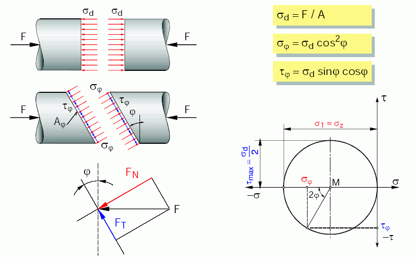
- 壓縮:與拉伸對稱,圓在 σ 軸負側,\(\sigma_d=F/A\)。
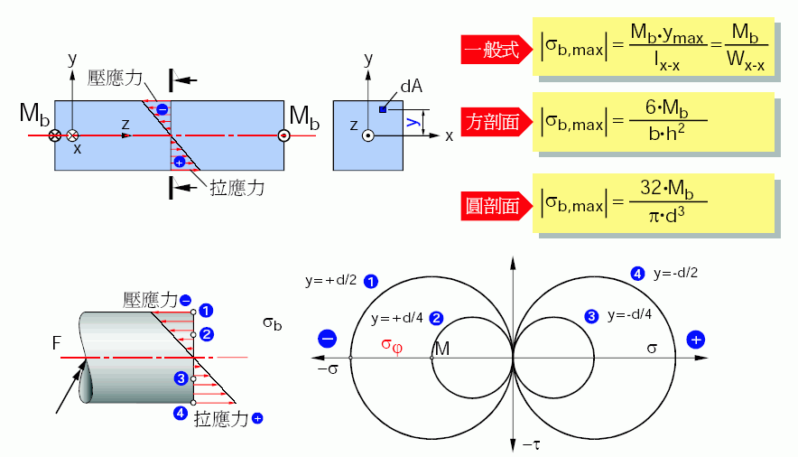
- 彎曲:\(|\sigma_{b,max}|=\dfrac{M_b\,y_{max}}{I_{x\text{-}x}}=\dfrac{M_b}{W_{x\text{-}x}}\);方形截面 \(\dfrac{6M_b}{bh^2}\)、圓形截面 \(\dfrac{32M_b}{\pi d^3}\)。截面上每一高度都是單軸應力,只是大小不同,所以莫爾圓是一組都通過原點的圓(① 上緣受壓最大、④ 下緣受拉最大)。
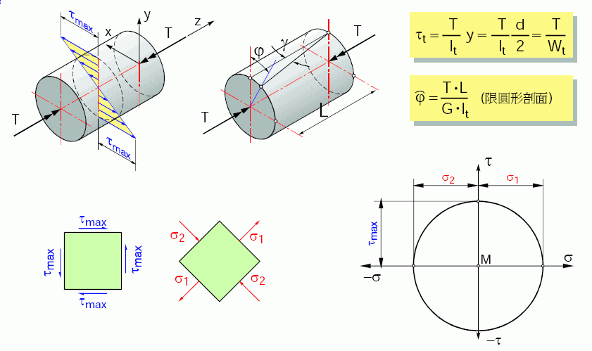
- 扭轉:\(\tau_t=\dfrac{T}{I_t}\,\dfrac d2=\dfrac{T}{W_t}\),\(\varphi=\dfrac{TL}{GI_t}\)(限圓形截面)。純剪狀態的莫爾圓圓心在原點,主應力 \(\sigma_1=\tau\)、\(\sigma_2=-\tau\) 在 45° 方向:脆性材料(如粉筆)受扭會沿 45° 螺旋面斷裂,就是被 \(\sigma_1\) 拉斷。
編註:這幾張原圖用的是另一套常見符號:\(W\) 為截面模數(即第 4 章的 \(S=I/c\))、\(I_t\) 為極慣性矩(即 \(J\))、\(W_t=I_t/(d/2)\) 為極截面模數。
原圖對照(四種負載)
截面形狀的效率 Section Efficiency
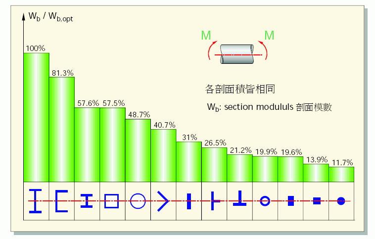
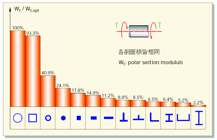
面積(用料)相同時,不同截面形狀的抗彎、抗扭能力差很多(原講義資料,以最佳形狀為 100%):
- 抗彎:材料要放在離中性軸遠的地方,I 形梁、槽形最有效;實心圓只有 11.7%。
- 抗扭:材料要放在離軸心遠的地方,而且截面要封閉。薄壁圓管、方管最有效;I 形梁、槽形這類開口薄壁截面抗扭極差(I 形梁只有 2.2%),所以傳動軸用圓管而不用型鋼。
原圖對照(截面效率)